Here’s a quick project that a couple of friends and I worked on for our Electronics & Instrumentation class. Our focus was on the engineering of the circuitry - with a nifty little application to one of my favourite hobbies. Enjoy!
Credit: Afareen Jaleel, Annika Torp, Ruby Liu, Yeonwoo Lee, Marion Pang
The Banshee
The Fuzz Face is an iconic guitar pedal used by famous guitarists such as Jimi Hendrix. However, fuzz effects clip off the lower spectrum of frequencies, leading to a shallow tone. In this project, we would like to recreate the fuzzy sound produced by the pedal while maintaining the full tone of an electric guitar. To create the fuzz effect, we use a simple combination of 2 transistors, and several different resistors and capacitors. The circuit designed combines initial soft clipping with asymmetrical clipping that changes toward symmetrical clipping under drive, resulting in the classic fuzz. We combine the fuzz circuit with a low pass filter and add the signals in a non-inverting summation amplifier. As a result, we are able to achieve the fuzz effect with bass boost.
The device is named “Banshee”, which refers to a female spirit whose shrieking signals that someone is about to die. This device shares a great similarity with a banshee, as you can hear it shrieking whenever it is unhappy with controlling of the dials. Like a banshee, its shrieking is unpredictable and the source of this “ability” is unknown.


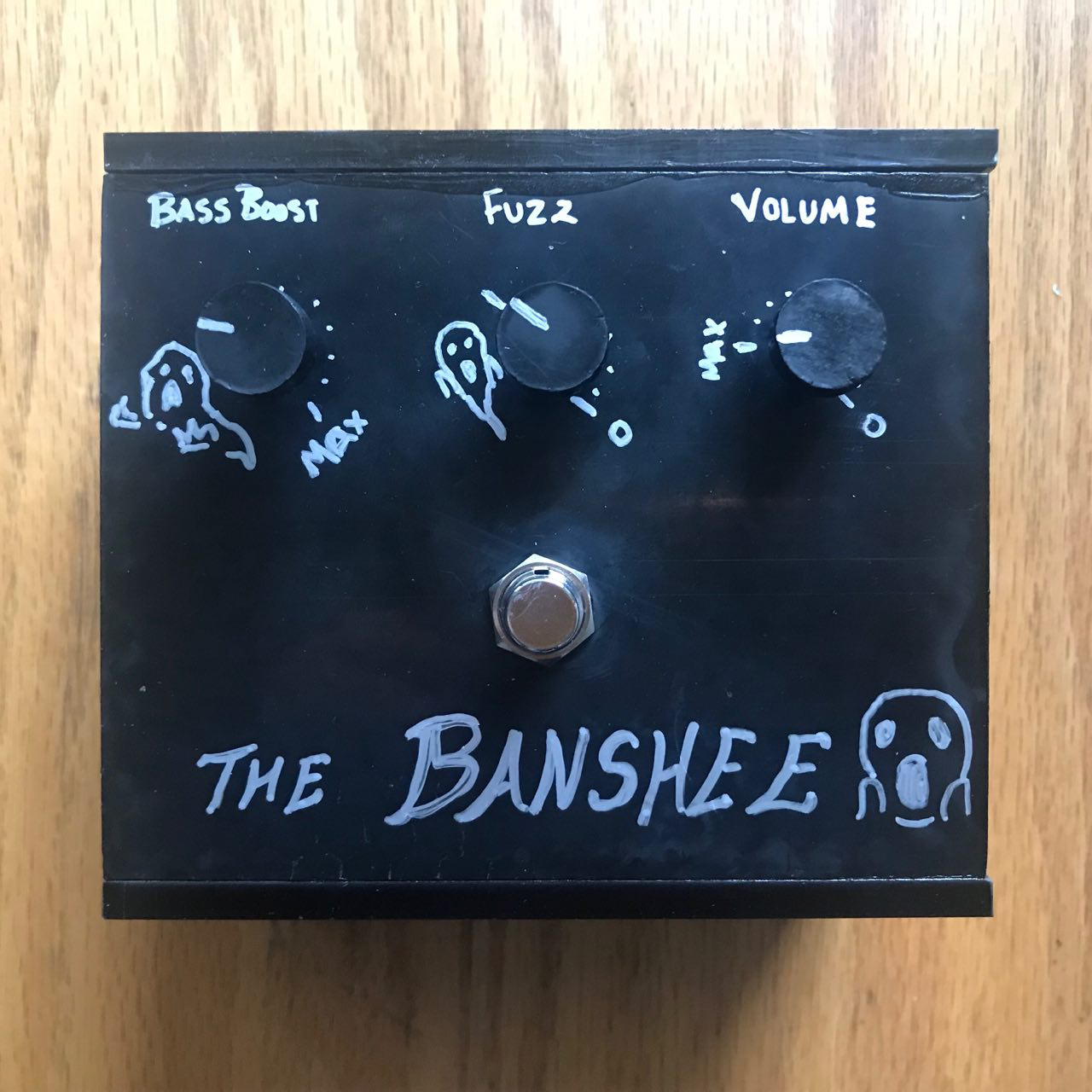
The device is operated using three potentiometer dials and a latching DPDT push button. To switch between a clean tone (without effects) and the fuzz effect, press the button once. The leftmost dial controls the cutoff frequency of the low-pass filter, or the range of low frequency sound waves that will be included in the final output sound. The center dial controls the level of “fuzziness” of the output. The rightmost dial controls the volume of the output. The input audio is connected using the 1/4” jack on the left side. The output audio comes from the 1/4” jack on the right side, which can be connected to a speaker.
Internal Operation of Device and Circuit Design

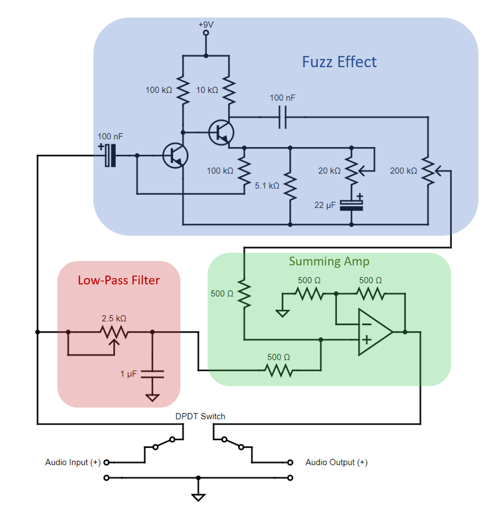
The device consists of 3 electrical circuits – the fuzz effect, a low-pass filter and the non-inverting summing amplifier. The choice between a clean tone or the fuzz effect is controlled by the DPDT switch.
Deviations from circuit drawing: 200k pot replaced by 176k pot. Two 10 μF capacitors in parallel (fuzz effect) instead of one 22 μF capacitor.
DPDT switch

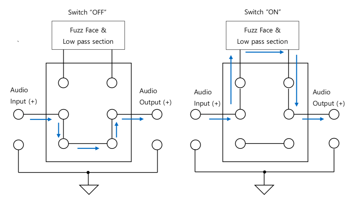
If the DPDT switch is on, the input signal is sent to the fuzz effect section and the low-pass section. In the above circuit diagram, the switch is on. Switching it off will connect the input and output directly, bypassing the circuits.
Low-pass filter
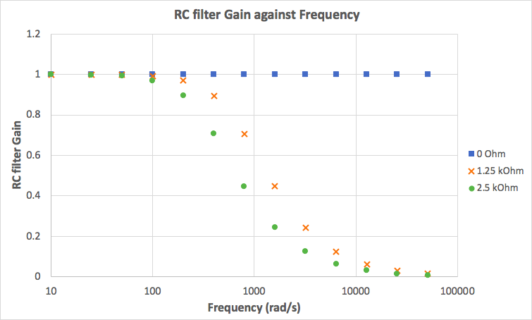
The low-pass filter consists of a 2.5 kΩ potentiometer and a 1 \( \mu \)F capacitor. Since the cutoff frequency is \( \frac{1}{RC} \), where \( R \) is the resistance of the potentiometer, and \( C \) is the capacitance of the capacitor, the circuit filters out signals above 400 Hz when the potentiometer is at maximum resistance. Turning the resistance to zero can turn off the filtering entirely.
Summing amplifier
We used a non-inverting summing operational amplifier to sum the fuzz circuit output with the low-frequency input so that the final output from the circuit would still have the low-frequency sound waves with the fuzzed effects on the higher frequency sound waves.
Circuit Design and choice of resistor/capacitor values
Non-inverting summation operational amplifier

The summing amplifier adds the signal from the fuzz effects section and the low-pass filter. That is, \( V_{out} = V_{fuzz} + V_{low} \). Using op-amp analysis, we obtain \[ V_{out}=(1+\frac{R_{f2}}{R_{f1}})(V_1 \cdot \frac{R_2}{R_1+R_2}+V_2\cdot\frac{R_1}{R_1+R_2}) \]
In our circuit, we chose 500Ω resistors to obtain \[V_{out}=(1+1)(V_1\cdot\frac{1}{2} + V_2\cdot\frac{1}{2})=V_1+V2 \]
Fuzz circuit
The fuzz circuit consists of 3 main parts: 2 amplifiers (input stage, output stage) and stabilising voltage feedback biasing network.

Amplifiers
The input stage essentially acts as a PNP amplifier (voltage follower), where the collector resistor follows the amplified voltage of the input. The amplifier provides a high voltage gain with low input impedance and high output impedance. A 100nF capacitor is added to the circuit to remove hum and protect the pedal against dangerous DC levels. Specifically, with a 100nF capacitor and 100kΩ resistor, the voltage gain of the input stage can be calculated to be
\[A_V = -g_{transistor} \cdot R_c = -g_{transistor}\cdot I_e / V_T \approx 290 \]
Similarly, the output stage is also a PNP emitter amplifier, which controls the emitter current of the voltage follower input circuit. The gain of the output stage can be calculated by the ratio of the volume pot over the total AC load, thus allowing an increase in amplitude as the pot is turned up. The emitter resistance \(R_{output}\) can be controlled by the fuzz pot to control the level of asymmetrical clipping. With the pot turned up, \(R_{output}\) is high, resulting in clipping at lower frequencies. \[\omega_{cutoff} = \frac{I}{RC}\] Thus, the “fuzzy” sound is more pronounced.
Voltage feedback biasing circuit
The feedback network consists of two resistors (emitter followers) and a transistor, arrange in the form of a voltage feedback biasing circuit. The voltage feedback biasing circuit serves the purpose of stabilising the gain from both input and output stages, making the gain less sensitive to temperature changes of transistors and reducing nonlinear distortion. When the fuzz pot is set to minimum, a large amount of signal is sent back to input in negative feedback, reducing total pedal gain. When the fuzz pot is set to maximum, the 22uF capacitor draws current to ground, increasing total pedal gain.
Combining the 2 input and output stages with the voltage feedback circuit, we can calculate for the total gain in the fuzz circuit:
\[ A_V = \frac{R_C}{R_E}=\frac{R_{input}+R_{output}}{R_{output pot}}\]
With values \(R_{input}=100k\Omega\),\(R_{output,max}=20k\Omega\), we have \[A_{V,max} = \frac{100k+20k}{20k}=6\]
Low Pass Filter

Since the sound distortion of the fuzz circuit acted on higher frequencies, we added a second parallel branch with a low pass filter to pass the low frequency audio signals. The lowest frequency of sound waves humans can hear is usually around 20 Hz but can be as low as 12 Hz. We used a 1 μF capacitor and 2.5 kΩ potentiometer so the minimum cutoff frequency of the RC filter is \(\frac{1}{RC}=6.37\cdot10^{-11} Hz\), and the user can adjust the potentiometer to allow a higher cutoff frequency (maximum cutoff frequency is when the resistor has the lowest resistance, and since the potentiometer resistance can be adjusted to approach 0Ω so that the cutoff frequency \(\frac{1}{RC}\) approaches \(\infty\).
\[\lim_{R\rightarrow 0} \frac{1}{RC}=\infty \]
Since a low pass filter allows frequencies lower than the cutoff frequency to pass through, when the potentiometer is set to maximum resistance, the cutoff frequency is lowest, so the range of frequencies allowed to pass through is small (and would only include frequencies that are inaudible to humans), so essentially no low frequency waves would be passed to the op-amp and only the output from the fuzz circuit would be heard. When the potentiometer is set to minimum resistance, the cutoff frequency is highest, so the range of frequencies allowed to pass through is largest (basically all frequencies can pass through), so essentially all waves would be passed to the op-amp and the output would be the sum of the output from the fuzz circuit with the original input audio. Thus, the user can adjust the potentiometer to decide what the maximum frequency of sound waves from the original audio should be summed with the fuzz circuit output.

Conclusion
The Fuzz Face circuit consists of simple components such as capacitors, resistors and transistors. To fully understand how the Fuzz Face works, it takes more than knowing how each component operate, since different circuit components affect each other, and a series of events occur in the circuit to create the fuzzy sound. Therefore, it is important to understand how each component operate as well as their role within the circuit and how they work together. In this project, the conventional Fuzz Face circuit was modified to improve on its limitation of eliminating lower frequencies, thus the bass of songs. Addition of a lower pass filter segregate out the lower frequencies (bass) and the summing amplifier combines the output from the Fuzz Face circuit and the filter to create bass boosted, fuzzy sound. Also, the resistance and capacitance values for the low pass filter and summing amplifier were chosen through trials and troubleshooting, to create the sound effect that we wanted. In conclusion, we have successfully incorporated the low pass filter and summing amplifier to the Fuzz Face to create the fuzzy sound without compromising the bass of the song in this project.