A self-balancing biped bot!! How cool is that?? (Robot, Sensors and Actuators final project)
Credit: Ruby Liu, Marion Pang
Introduction
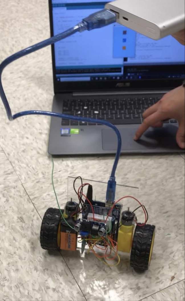
In this project, we develop a simple self-balancing 2-wheeled RC robot, using the accelerometer and PID control to maintain balance while accepting user input for movement. The robot’s movement is controlled using bluetooth by a simple GUI on the Processing software on a computer.
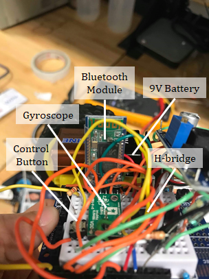
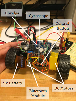
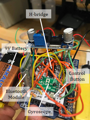
Robot Schematics
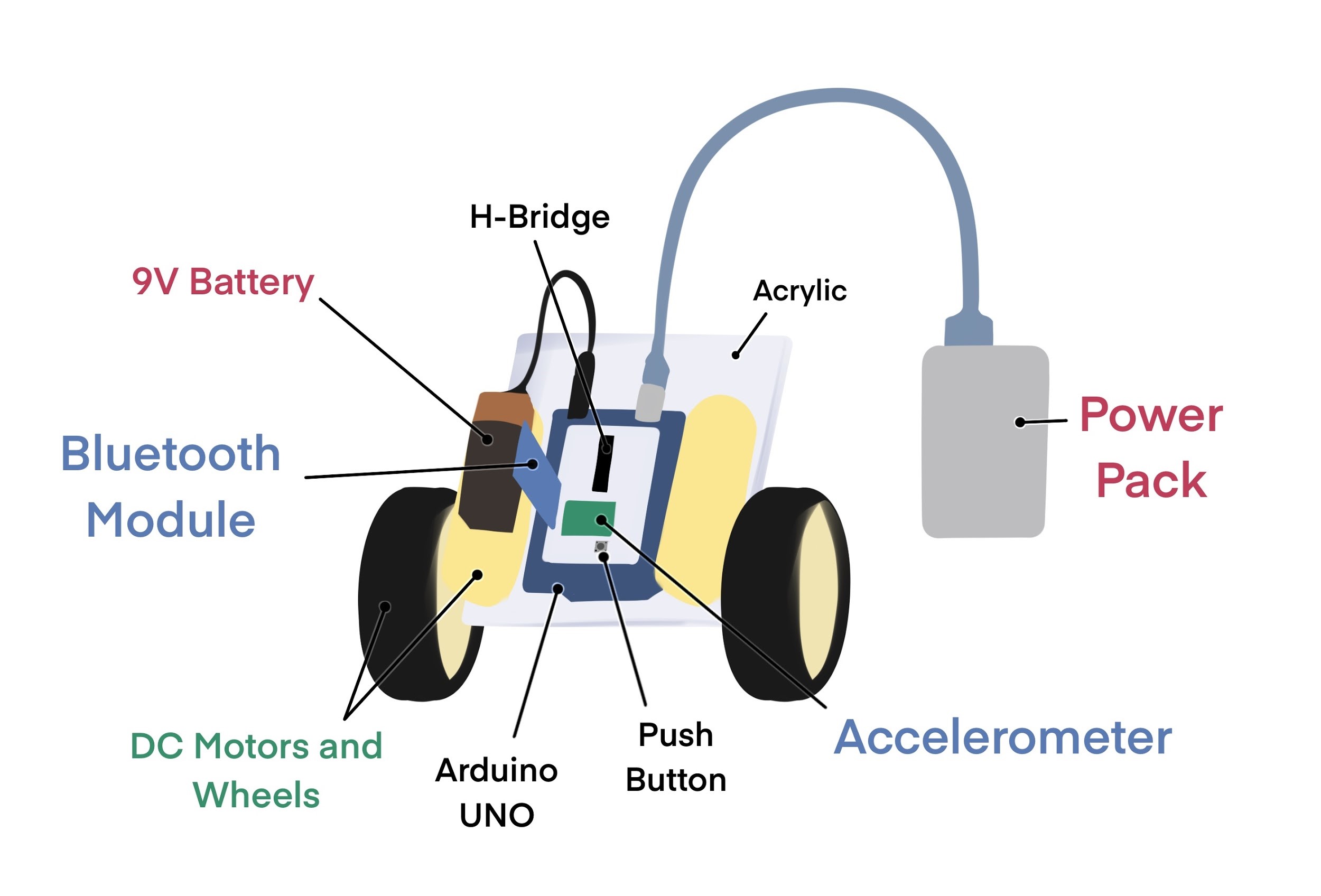
Our robot consists of a piece of acrylic mounted with an Arduino Uno (with a breadboard shield) and two DC motors with wheels attached. The Arduino and motors are hot-glued to the acrylic. A 9V battery is attached to one of the motors using double-sided tape, and an additional power pack is often necessary to run the robot.
Sensors
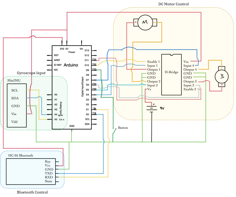
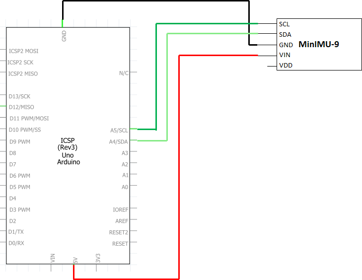
MinIMU-9 v5 Gyro
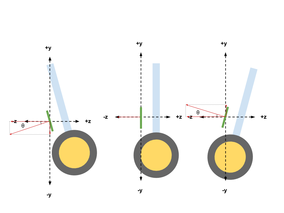
The MinIMU-9 v5 Gyro/Accelerometer was used to measure the orientation of the robot. Specifically, the arctan of the ratio of y and z axis accelerometer readings were taken to calculate the angle of inclination of the robot. These readings act as the input to the control loop, and are compared to the initial set point, which can be calibrated by the user to be at the robot’s center of gravity, to determine the robot’s next movement and speed (e.g. forward/backward/stop).
HC-05 Bluetooth Module
The HC-05 bluetooth module can be used to enable 2-way communication between an Arduino and any device with bluetooth functionality. In our project, we developed a simple GUI using Processing.js that sends commands via bluetooth to the HC-05 module, which is then used to control the movements of the RC robot. The HC-05 Bluetooth module communicates with the arduino via the Serial Port Protocol (SPP) to transmit serial data.
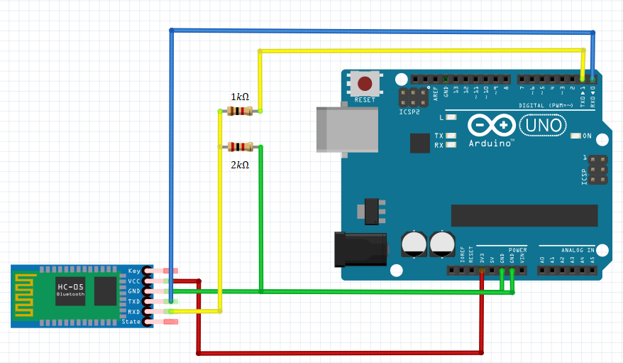
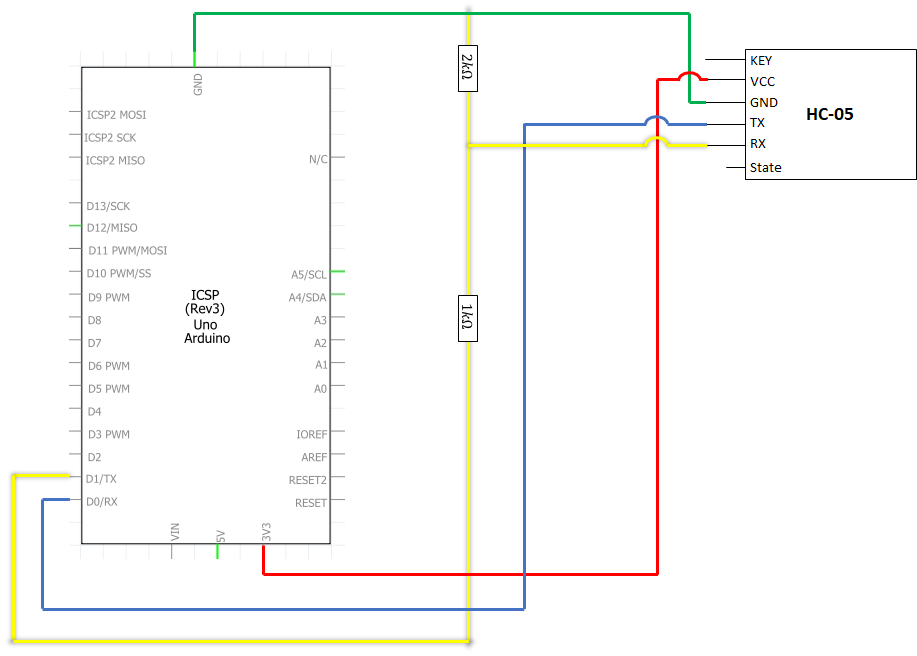
Typically, Arduino and Bluetooth RX (receive pin) only accepts a logic voltage level of 3.3V. As the Arduino TX (transmit pin) has a 5V output, we used a voltage divider to drop the voltage down to an acceptable level of 3.3V for the Bluetooth RX to prevent burnout of the module. The Bluetooth module runs at a voltage of 3.3V, and also outputs serial data at 3.3V - as such, there was no need for a voltage divider circuit to lower the voltage for the Arduino RX.
Actuators
DC Motors
The main actuators of the robot comprises of 2 DC hobby motors that run from 0-9V. In our robot, the voltage output is limited to the voltage of the battery - which ranges from between 7.6 to 8.8V. The direction of the motor is controlled using 2 digital OUTPUT pins (corresponding to forward and back) and the magnitude of voltage is controlled using an analog OUTPUT pin. The respective direction and magnitude signals are then fed into an H-bridge, which controls both motors. Notably, we invert the direction of the right motor from the left to ensure that both wheels move in the same direction respective to the Arduino.
Program
PID Control
PID control is a controller system that uses a control loop feedback mechanism to stabilize process variables. The problem we want to solve is simple - we are measuring the tilt of our bot (process variable) and we want to ensure that the bot remains upright (setpoint) as it moves. With relation to a PID controller, we feed our error value (PV - DV) into the controller with a proportional, integral and differentiator gain, and applies the correction to the bot.
\[u(t) = K_pe(t)+K_i\int e(t)dt+K_p\frac{de}{dt} \] \(K_p \) = proportional gain
\(e(t) \) = error value
\(K_i \) = integral gain
\(d(e) \) = change in error value
\(d(t) \) = change in time
The robot is programmed with proportional feedback control to maintain its balance in conjunction with user input. The robot keeps track of its current orientation using the accelerometer readings - these readings are fed back in a negative feedback loop to help the robot correct its position back to baseline, which is either the starting position, the “forward” position, or the “backward” position, which can be changed using a bluetooth GUI.
We also considered integral and derivative control, both of which worsened the stability instead of improving it—so we removed both. Finally, the optimized value of Kprop was found to be 90.
Arduino PID Control
At the start of the Arduino program, the program records the current position and uses that as the balance point. This can be recalibrated by hitting the reset button. Then, the user must press a push button to activate the balancing program.
Laptop Processing Bluetooth Controller
We programmed a program on Processing.js to allow a laptop to function as a bluetooth controller. It displays a three-button GUI for forward movement, backward movement, and no movement. The laptop is first connected via Bluetooth to the HC-05 module, which enables Serial communication between the Arduino and the program. When a button is pressed, the laptop sends the respective signal (F for forwards/B for backwards/S for stop) to the Bluetooth module, which then transmits the character to the Arduino microcontroller. The Arduino interprets each character as a move signal and offsets its current balancing signal by that respective amount. This tilts the bot forwards/backwards, enabling the desired forward or backwards motion. The laptop will continuously transmit the signal corresponding to the last button pressed, which is received by the Arduino to adjust the baseline position.
Arduino bot code
#include <Wire.h>
#include <LSM6.h>
#include <math.h>

LSM6 imu;

int16_t accY, accZ, accX; // accelerometer readings
double accAngle; // calculated angle
float startAngle;
double prevAngle = PI / 2 + startAngle;

//float angVel;
float angleError;
float prevError = 0;
float errDeriv;
float sig;
float Kprop = 90; // V/rad; ranges from 70+
float KD = 0;
float KI = 0;

unsigned long currTime;
unsigned long prevTime = 0;
int deltaT;

int posPin = 4; // + terminal motor pin
int negPin = 5; // - terminal motor pin
int enPin = 10; // enable 1 pin
int pos2Pin = 6; // + terminal motor pin
int neg2Pin = 7; // - terminal motor pin
int en2Pin = 11; // enable 1 pin

int buttonPin = 9;

// For Bluetooth
char val;
int LEDpin = 12;
float moveSig = 0;

void setup() {
  // set pins
  pinMode(buttonPin, INPUT_PULLUP);

  pinMode(posPin, OUTPUT); // + terminal motor pin
  pinMode(negPin, OUTPUT); // - terminal motor pin
  pinMode(enPin, OUTPUT); // enable 1 pin

  pinMode(pos2Pin, OUTPUT); // + terminal motor pin
  pinMode(neg2Pin, OUTPUT); // - terminal motor pin
  pinMode(en2Pin, OUTPUT); // enable 1 pin

  pinMode(LEDpin, OUTPUT);

  Serial.begin(9600);

  // set up accelerometer
  Wire.begin();
  if (!imu.init())
  {
    //Serial.println("Failed to detect and initialize IMU!");
    while (1);
  }
  imu.enableDefault();
}

void loop() {

  // read accelerometer data
  imu.read();

  accZ = imu.a.z;
  accY = imu.a.y;
  accX = imu.a.x;

  startAngle = atan2(accY, accZ); // calculate start angle from current position

  while (digitalRead(buttonPin) == HIGH) {}

  // Balancing program
  while (true) {
    // Read bluetooth
    if ( Serial.available() ) // if data is available to read
    {
      val = Serial.read(); // read it and store it in 'val'
    }
    if ( val == 'F' ) {
      // move forward, gradually changing the signal
      moveSig = max(moveSig - .1, -20);
    }
    else if ( val == 'B' ) {
      // move backward, gradually changing the signal
      moveSig = min(moveSig + .1, 20);
    }
    else {
      // return signal (closer) to 0
      moveSig = moveSig * 0.8;
    }

    // read accelerometer
    imu.read();

    accZ = imu.a.z;
    accY = imu.a.y;
    accX = imu.a.x;

    // calculate angle position
    accAngle = atan2(accY, accZ);
    accAngle = constrain(accAngle, -PI, PI);

    angleError =  startAngle - accAngle;

    // debugging print statements
    //if (isnan(accAngle));
    //else {
    //  Serial.print(accAngle);
    //  Serial.print(" ");
    //  Serial.println(angleError);
    //}

    currTime = millis();
    deltaT = currTime - prevTime;
    prevTime = millis(); // record time

    errDeriv = (angleError - prevError) / (deltaT / 1000.);
    prevError = angleError;

    sig = Kprop * angleError + KD * angleError + moveSig;


    // If the signal is positive, rotate positive
    if (sig > 0 && accAngle > -PI / 2) {
      //Serial.println("forward");
      digitalWrite(posPin, HIGH); digitalWrite(negPin, LOW);
      digitalWrite(pos2Pin, HIGH); digitalWrite(neg2Pin, LOW);
    }
    // if signal is negative, rotate negative
    else if (sig < 0) {
      //Serial.println("backward");
      digitalWrite(negPin, HIGH); digitalWrite(posPin, LOW);
      digitalWrite(neg2Pin, HIGH); digitalWrite(pos2Pin, LOW);
    }

    // convert signal to analog range
    int sigNorm = constrain(abs(sig / 9.*255), 0, 255);
    // set the enable pin to the converted analog signal
    analogWrite(enPin, sigNorm);
    analogWrite(en2Pin, sigNorm);


  }
  delay(500);
}
Processing code from receiver side (requires bluetooth pairing)
//import class to set up serial connection with wiring board
import processing.serial.*;
Serial port;
//button setup
color currentcolor;
RectButton upButton, downButton, stopButton;
boolean locked = false;

void setup() {
   //set up window
   size(300, 400);
   color baseColor = color(102, 102, 102);
   currentcolor = baseColor;

   // Obtain list of serial ports and connect to HC-05 Module
   println(Serial.list());
   port = new Serial(this, Serial.list()[1], 9600); // COM8 (outgoing)
   println(port);
   // Define and create rectangle button #upButton
   int x = 125;
   int y = 50;
   int size = 50;
   color buttoncolor = color(153, 102, 102);
   color highlight = color(102, 51, 51);
   upButton = new RectButton(x, y, size, buttoncolor, highlight);

   // Define and create rectangle button #stopButton
   x = 125;
   y = 150;
   size = 50;
   buttoncolor = color(179, 230, 255);
   highlight = color(0, 153, 230);
   stopButton = new RectButton(x, y, size, buttoncolor, highlight);

   // Define and create rectangle button #downButton
   x = 125;
   y = 250;
   size = 50;
   buttoncolor = color(255, 153, 51);
   highlight = color(230, 115, 0);
   downButton = new RectButton(x, y, size, buttoncolor, highlight);

}

void draw() {
   // first, draw GUI
   background(currentcolor);
   stroke(255);
   update(mouseX, mouseY);
   upButton.display();
   stopButton.display();
   downButton.display();
}

void update(int x, int y) {
   // update GUI at each frame
   if(locked == false) {
      upButton.update();
      downButton.update();
      stopButton.update();
   } else {
      locked = false;
   }

   // if any of the F/B/S buttons are pressed
   if(mousePressed) {
      if(upButton.pressed()) { // Forward button
         currentcolor = upButton.basecolor;
         port.write('F');
      } else if(downButton.pressed()) { // Backwards button
         currentcolor = downButton.basecolor;
         port.write('B');
      }
      else if(stopButton.pressed()) { // Stop button
         currentcolor = stopButton.basecolor;
         port.write('S');
      }
   }
}

// set up button class and respective event listeners
class Button {
   int x, y;
   int size;
   color basecolor, highlightcolor;
   color currentcolor;
   boolean over = false;
   boolean pressed = false;
   void update() {
      if(over()) {
         currentcolor = highlightcolor;
      } else {
         currentcolor = basecolor;
      }
   }
   boolean pressed() {
      if(over) {
          locked = true;
          return true;
      } else {
          locked = false;
          return false;
      }
   }
   boolean over() {
      return true;
   }
   void display() {
   }
}

// rectButton is a class that extends button with pre-determined GUI parameters
class RectButton extends Button {
   RectButton(int ix, int iy, int isize, color icolor, color ihighlight) {
      x = ix;
      y = iy;
      size = isize;
      basecolor = icolor;
      highlightcolor = ihighlight;
      currentcolor = basecolor;
   }
   boolean over() {
      if( overRect(x, y, size, size) ) {
         over = true;
         return true;
       } else {
         over = false;
         return false;
       }
    }
   void display() {
      stroke(255);
      fill(currentcolor);
      rect(x, y, size, size);
   }
}

boolean overRect(int x, int y, int width, int height) {
   if (mouseX >= x && mouseX <= x+width && mouseY >= y && mouseY <= y+height) {
      return true;
   } else {
      return false;
   }
}